- 您现在的位置:买卖IC网 > Sheet目录1229 > MAX9880AEVKIT+ (Maxim Integrated Products)KIT EVAL FOR MAX9880A
�� �
�
�MAX9880A� Evaluation� Kit�
�Enable� Register�
�The� Enable� register� provides� enables� for� the� left/right�
�line� inputs,� left/right� line� outputs,� and� left/right� DACs� and�
�ADCs.� The� line� input� and� output� enables� are� accessed�
�from� Left� Line� Input� and� Right� Line� Input� windows� and�
�the� line� outputs� are� configurable� through� the� Left� Line�
�Out� Enable� and� Right� Line� Out� Enable� windows.� Figure�
�17� shows� which� GUI� blocks� provide� access� to� the� line�
�input� and� line� output� enables.�
�The� left� and� right� DAC� and� ADC� enables� are� accessed�
�by� selecting� the� DAC� and� ADC� blocks� available� on� both�
�the� Analog� Audio� and� Digital� Audio� tabs.� Note� that�
�when� enabling� the� right� DAC/ADC,� the� left� DAC/ADC�
�should� also� be� enabled.�
�System� Shutdown� Register�
�The� register’s� SHDN� bit� is� used� to� place� the� device� in� a�
�lower-power� shutdown� mode.� This� feature� is� controlled�
�by� the� MAX9880A� Power� button� at� the� top� of� the� main�
�software� window.� This� register� is� also� used� to� configure�
�the� device� crystal� oscillator.� This� is� configured� by� select-�
�ing� the� CRYSTAL� block� on� the� Digital� Audio� tab.�
�Device� Revision� ID�
�The� device’s� revision� ID� is� stored� in� registers� 0x14� and�
�0xFF.� After� the� software� has� established� a� connection� to�
�the� EV� kit� and� device,� it� reads� one� of� these� two� registers�
�to� determine� the� device’s� revision� ID.� In� SPI� mode,� the�
�0x214� (0x14� in� I� 2� C� mode)� register� is� read,� and� in� I� 2� C�
�mode� the� 0xFF� register� is� read.� If� the� revision� ID� is� not�
�recognized,� the� software� displays� a� dialog� box� informing�
�that� a� noncompatible� device� has� been� detected.�
�Note:� When� in� SPI� mode,� the� 0xFF� register� is� not�
�accessible.�
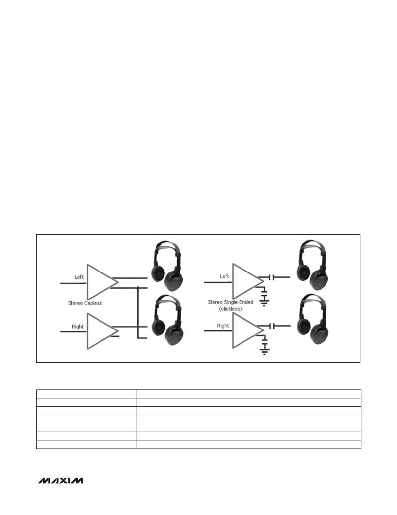
�Figure� 16.� Headphone� Modes� (2� of� 8)�
�Table� 11.� Jack� Detect/Jack� Status� Controls�
�GUI� CONTROL�
�Jack� Detection� radio� buttons�
�Jack� Detect� Debounce� radio� buttons�
�Jack� Sense� group� box�
�Jack� Action� group� box�
�Jack� Sense� Weak� Pullup� group� box�
�DESCRIPTION�
�Configures� JDTEN� bit� (enable:� JDETEN� =� 1).�
�Configures� the� JDEB� bits.�
�Displays� the� status� of� the� JACKSNS� bits.� This� requires� that� Jack� Detection� be� enabled�
�(JDETEN� =� 1).�
�Displays� the� results� of� the� Jack� Detection� logic,� when� JDETEN� =� 1.�
�Configures� the� JDWK� bit.�
�______________________________________________________________________________________�
�19�
�发布紧急采购,3分钟左右您将得到回复。
相关PDF资料
MAX9921EVKIT+
KIT EVAL FOR MAX9921
MAX9940AXK+T
IC OVERVOLTAGE PROTECTOR SC70-5
MAX9959EVKIT+
EVAL KIT MAX9959
MAX9979EVKIT+
EVAL KIT MAX9979
MAXFILTERBRD+
BOARD EVAL MAX7408/7415/418-7425
MAXQSERIALJTAG-KIT
MAXQ SERIAL/JTAG EVAL BOARD
MAXQUSBJTAG-KIT#
MAXQ USB JTAG EVAL BOARD
MAXSPCSPARTAN6+
ADC and DAC Eval Expansion Board
相关代理商/技术参数
MAX9880AEWM+T
功能描述:接口—CODEC Stereo Audio CODEC RoHS:否 制造商:Texas Instruments 类型: 分辨率: 转换速率:48 kSPs 接口类型:I2C ADC 数量:2 DAC 数量:4 工作电源电压:1.8 V, 2.1 V, 2.3 V to 5.5 V 最大工作温度:+ 85 C 安装风格:SMD/SMT 封装 / 箱体:DSBGA-81 封装:Reel
MAX9880ETM+
制造商:Maxim Integrated Products 功能描述:AUDIO CODEC - Rail/Tube
MAX9880EVKIT+
制造商:Maxim Integrated Products 功能描述:STEREO AUDIO CODEC - Boxed Product (Development Kits)
MAX9880EWM+T
制造商:Maxim from Components Direct 功能描述:THE MAXIM MAX9880EWM+T IS AN AUDIO CODEC CONVERTER. - Tape and Reel 制造商:Maxim 功能描述:Maxim MAX9880EWM+T, Audio CODEC Converter Dual I2S 1.8V 48-bump WLP
MAX9888EVKIT+
功能描述:音频 IC 开发工具 MAX9888 Eval Kit RoHS:否 制造商:Texas Instruments 产品:Evaluation Kits 类型:Audio Amplifiers 工具用于评估:TAS5614L 工作电源电压:12 V to 38 V
MAX9888EWY+T
功能描述:接口—CODEC Stereo Audio CODEC RoHS:否 制造商:Texas Instruments 类型: 分辨率: 转换速率:48 kSPs 接口类型:I2C ADC 数量:2 DAC 数量:4 工作电源电压:1.8 V, 2.1 V, 2.3 V to 5.5 V 最大工作温度:+ 85 C 安装风格:SMD/SMT 封装 / 箱体:DSBGA-81 封装:Reel
MAX9889EWO+T
功能描述:接口—CODEC RoHS:否 制造商:Texas Instruments 类型: 分辨率: 转换速率:48 kSPs 接口类型:I2C ADC 数量:2 DAC 数量:4 工作电源电压:1.8 V, 2.1 V, 2.3 V to 5.5 V 最大工作温度:+ 85 C 安装风格:SMD/SMT 封装 / 箱体:DSBGA-81 封装:Reel
MAX988ESA
功能描述:校验器 IC Single uPower Comparator RoHS:否 制造商:STMicroelectronics 产品: 比较器类型: 通道数量: 输出类型:Push-Pull 电源电压-最大:5.5 V 电源电压-最小:1.1 V 补偿电压(最大值):6 mV 电源电流(最大值):1350 nA 响应时间: 最大工作温度:+ 125 C 安装风格:SMD/SMT 封装 / 箱体:SC-70-5 封装:Reel